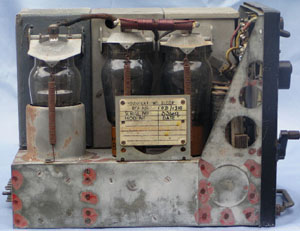
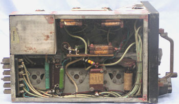
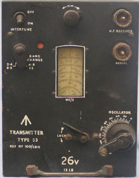
Illustrations of the set
The transmitter uses a VT 60A (807- ATS25) in a tri-tet oscillator driving an output circuit using two VT6OA's in parallel. For the higher frequency range, the frequency is doubled in the output amplifier.
There are three tuned circuits. The first is the frequency determining circuit covering 1.2 - 3.25 MHz, the second the oscillator output circuit covering 2.4 - 6.5 MHz, and the third the amplifier output circuit covering 2.4 - 6.5 MHz and 4.8 - 13.0 mHz. Band switching is confined to the output circuit.
Tuning is by rotating coil throughout. All circuits are ganged and driven by one large dial with a spiral scale (with the exception of the aerial circuit which has its own tuning control). The spiral scale on this dial is calibrated in two ranges 2.4 - 6.5 MHz and 4.8 - 13.0 MHz. The overall scale length is 46 inches and the law is such that 12kHz per millimetre is obtained at the worst part of the scale. The calibration is standard for all sets. Individual final calibration is effected by tracing the calibration line on the cursor.
The use of an output circuit ganged to the oscillator circuits and a separately tuned aerial circuit, has the advantage that the output stage cannot be overloaded by mistuning the aerial.
© Ian O'Toole, 2009. Page created: 12/05/03 Last updated: 3/12/2009