Illustrations of the set
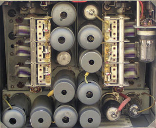
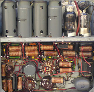
View of the interior TOP - MF section to right and BOTTOM - MF to left (unit front at top in each case) .
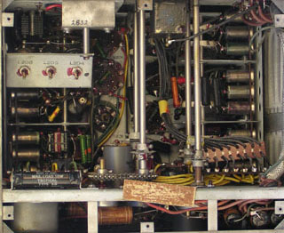
View of back
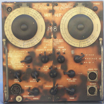
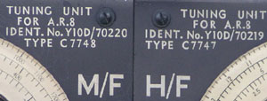
The receivers were unique in design, having two front ends (MF and HF) which were switched into a common IF channel. (Note: Non standard IF Frequency 755kc.) This feature enabled two frequencies to be rapidly selected. For example, the MF tuner could be tuned to an NDB or broadcast station for DF purposes while the HF unit was set to a communication channel.
The sets were supplied with loop antennas for direction finding on the MF bands. The audio amplifier in the receiver was also utilized as an intercom amplifier that could drive five pairs of service headphones in parallel.
Sensitivity: 6mw audio output -
Below 9.5Mc Not more than 3uv input
Above 9.5Mc Not more than 10uv input
| The valve complement is: | ||
| V1 6U7G 1st IF Amp | V5 6J7G Audio Output | V103 6J5G HF Oscillator |
| V2 6A8G Beat Osc | V6 6X5 Limiter Diode | V201 6U7G MF RF Amp |
| V3 6U7G 2nd IF Amp | V101 6U7G HF RF Amp | V202 6A8G MF Converter |
| V4 6G8G Det/AF Amp | V102 6A8G HF Converter |
The limiter diode provided protection from the transmit signal and on some sets V103 6J5 was replaced with a 6V6 due to stock shortages.
Power Requirements:
The station could be configured for 12 or 24v operation. HT was supplied by a dynamotor during aircraft or portable operation, supplying 250vdc for the receiver. A mains supply, Type "S", to run the complete station was also available. It was very heavy.
The sets were popular with amateurs as very little work was required to put them on the air. The usual approach was to re-wire the filaments to 6.3v and build a standard type power supply to operate them. Some went to the extent of changing the output valve to a 6V6.
© Ian O'Toole, 2009. Page created: 27/03/05 Last updated: 3/12/2009