Technical Data
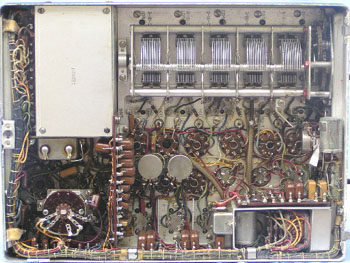
It uses 16 octal tubes and uses 28 volts DC for the high and low tension supply.
The set uses "switched" i.f. channels, with the low band (100-200 kHz) using 142.5 kHz and the other 3 bands using 455 kHz.
Unlike the earlier MN26 Radio Compass, this set uses automatic direction finding, by making use of 2050 thyratrons in association with the loop aerial servomotor system. Bearing taking is hence much easier and overcomes the "reciprocal bearing anomoly" which was possible with the earlier system, which could not indicate if a signal was arriving from the front or back of the loop. It was up to the pilot to deviate from the course to find out if he was heading toward or away from the signal.
The ARN-6 (1950 onward) replaced the earlier ARN-7 (1945-1950), which was heavier and bulkier and required 1l5v 400 Hz AC power.
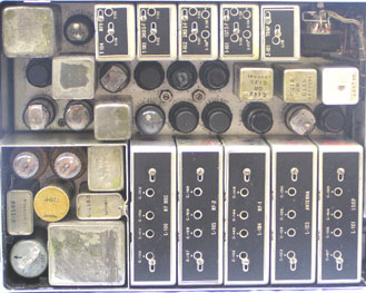
The components of the system are:
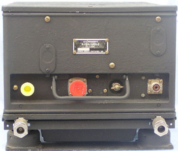
Receiver R101B/ARN-6
Mounting MT-273F/ARN-6
Control Unit C-1514A/ARN-6
Antenna Loop AS-3l3BIARN-6
Indicator ID9lB/ARN-6
To run the set requires 26.5v DC at 4.0 amps. The equipment weighs approximately 60 lbs and was manufactured by the Magnavox Company, Ft Wayne, Indiana, USA.
To operate the set successfully requires all of the above system components.
Frequency Coverage:
Band 1 100- 200 kHz
Band 2 200- 410 kHz
Band 3 410- 850 kHz
Band 4 850-1750 kHz