General Description
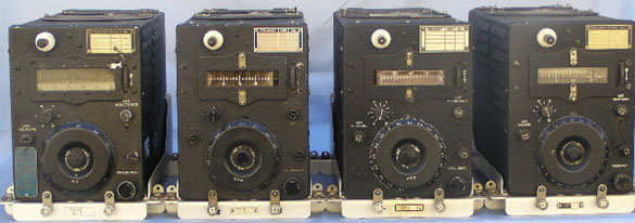
There were 3 basic receivers and 4 basic transmitters in the series. There were also many variants. The U.S. Navy had similar equipment under the ARC 5 nomenclature.
The design philosophy dated from the 1930's and used a system of racks which enabled equipment to be changed quickly in the event of a fault developing. The sets operated on one band only. To change bands you simply turned on another set. This was not quite the way such a problem was normally handled.
Technical Data
BC-696-A 3.0-4.0 mc
BC-457-A 4.0-5.3 mc
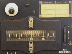
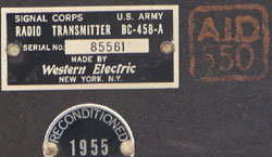
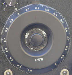
BC-458-A 5.3-7.0 mc
BC-459-A 7.0-9.1 mc
The dynamotor was DM-33-A, which clipped to the Modulator BC-456-A. This unit was connected to feed each transmitter as it was selected. Remote Control Box BC-451 allowed selection of the appropriate transmitter.
The Transmitter outputs were paralleled and switched in Antenna Relay Unit BC-442 to the wire antenna. (Receiver inputs were also paralleled.)
Under optimum conditions each transmitter could exceed 40 watts on CW.
Each transmitter drew approx. 9 amps at 28 volts in operation. They worked satisfactorily between 22 - 30 volts input.
The circuits of the various transmitters were similar, the main differences being changes in inductance values in tuned eircuits. A master oscillator (1626) excited a pair of beam tetrode power tubes (1625) connected in parallel. The tuning to the above was ganged, simplifying operation. An antenna coupling control was used to vary the coupling between the output tank and the roller inductor loading coil.
The transmitters could be modulated to 85% using screen grid modulation.
The transmitters were used by many amateurs after the war, but TVI problems sounded their death knell in their original form. Many were stripped for their high quality components, particularly the invar variable capacitors. The sets had an extremely good name for their frequency stability.
Restoring this equipment to original condition is hard owing to the difficulty in obtaining the connectors to join the various component parts of the system together. I would appreciate any help in this area!