Click to view detailed pictures of the receiver.
The handbook dates from May, 1961
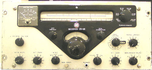
The receiver represents the end of the valve era and the circuit features approaches radically different from earlier receivers. The valve line up is:
| The valve complement is: | ||
| 6BY7 RF Amp | 6BA6/6BA6/6AU6 Aperiodic IF Amp (100kc input) | Solid State Noise Limiter |
| 6AJ8 1st Mixer/Osc(O/P 1.8 mc/s to Block Filter) | AM Detector - Solid State | 6AU6 Crystal Calibrator 500kc |
| 12AU7 Xtal Oscillator (6 xtal positions) | CW/SSB Detector 12AU7 Product Detector | 6AU6 Audio Amplifier |
| 6AJ8 2nd Mixer (1700 kc) | 6AU6 Beat Frequency Oscillator | 6AQ5 Audio Output (L/S & 600 ohm line output) |
The power supply consists of a full wave bridge providing 150vdc for HT and 6.3v for heaters. A VR tube (OB2) provides power for the noise limiter and variable oscillator.
There are 6 wavebands : 0.2 - 0.54 Mc/s 2.0 - 5.0 M/cs 5.0 - 10 Mc/s 10 - 15 Mc/s 15 - 20 Mc/s 20 - 25 Mc/s
The CR-6B suffers from oscillator drift when using manual tuning. Crystal control solves this problem. Performance on the NDB band is not brilliant. This was not a problem for DCA as they only needed it to check performance of local beacons.
Back to Top or Go to Home page.
© Ian O'Toole, 2009. Page created: 22/09/05 Last updated: 4/12/2009