The most frequently found version is the last, the LM-13.
The following information was taken from the LM -13 handbook.
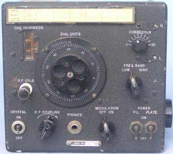
The Model LM-13 Crystal Calibrated Frequency Indicating Equipment has been specially designed to provide a simple, accurate and reliable frequency indicating equipment of the crystal calibrated type for use in the (U.S.) Naval radio service. It is adaptable for adjusting adjacent radio transmitters and receivers to any desired frequency within the range from 125 to 20,000 Kcs.
The equipment comprised the Frequency Meter (CRR 74028), a carrying ase (CRR 10111), similar to the familiar BC221 bag and a canvas bag with strap, type CMQ-10111. A set of 600 ohm headphones, 4 x 45 volt "B" battteries and 2 x 6 volt "A" batteries were also required. The whole unit weighed just under 40 Ibs.
The filaments drew l2volts at 0.67 amperes and the plate supply was 180 volts at 5 m.a. Often the LM frequency meters drew their operating power from the equipment they were to be used with. Typical examples were the "RU" series of receivers, the "GF" series of transmitters (pre- command type equipment) and the RBM equipment.
Each set, as in the case of the BC221, was separately calibrated and each was supplied with a calibration book bearing the same serial number. A unit without the book is of limited use.
Without the battery supply the units are quite compact and would have fitted quite easily beside the gear in a ham shack of the day. It was a simple matter to put together a power supply to operate the unit. Many of the LM models had provision for 12/24 volt operation and a choice of H.T. input voltages.
The most difficult part to find of the whole installation is the power input connector.
The handbook indicates the unit was manufactured for the U.S Navy Bureau of Ships by Bendix Radio, Baltimore, Maryland. The original contract was dated 27 December,1939.
© Ian O'Toole, 2009. Page created: 28/04/03 Last updated: 4/12/2009