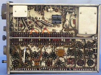
Illustrations of the set
Back to Top or Go to Home page.
© Ian O'Toole, 2009. Page created: 28/04/03 Last updated: 4/12/2009
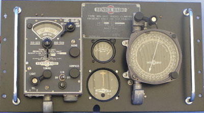
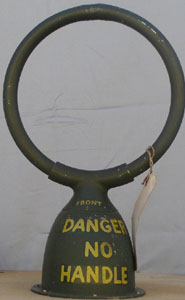
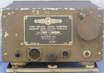
The receiver itself was located remotely in the aircraft and operated by remote control so as to save cockpit space. For a tuning meter the MR57A is used and the IN4A for left/right homing. The D/F loop (MN20 or MN24) was located either above or below the aircraft and was hand rotated using Bowden drive through an MN22A or MN52A control head.
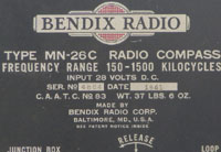
The MN26 was a commercial unit as opposed to one designed specifically for the military. Although many of these radios were used by the military, they were eventually replaced by the automatic D/F types in the middle of WW2, types such as ARN6, ARN7 and BC433G.
The MN26 was a popular receiver after the war as a high performance broadcast receiver. After the D/F section was removed, what remained was quite a sensitive 8 valve receiver. Published conversions included sawing off the rear end of the set, mounting it under the driver's seat and hey presto! one had a super hot receiver for the car.
Band change was by an electric motor and tuning by a flexible drive through the MN28A control box.
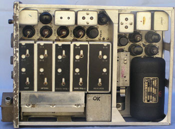
The tube line up is as follows:
V1 6K7 Loop
Amp *
V2 6N7 Audio
Osc (48 cycles) *
V3 6N7 Modulator
*
V4,5 6K7 RF Stages
V6 6L7 Mixer
V7 6J5 Osc
V8 6K7 IF
Amp (112.5 kHz)
V9 6J5 BFO
V10 6B8 Audio Amp
V11 6F6 Audio Output
V12 6K7 Compass Amp *
(Functions marked "*" are for compass operation and are not needed for general
reception.)
The MN26 will take D/F bearings on "Compass", act as a standard receiver on "Rec Ant" using a short vertical antenna and will also receive stations with the loop antenna on "Rec Loop".
Being fully remote controlled, few receivers remain in their original form. The display receiver is fully operational, as intended for aircraft operations.
© Ian O'Toole, 2009. Page created: 28/04/03 Last updated: 4/12/2009