Radio pic

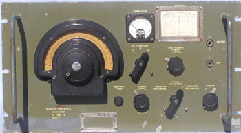
Receiver R1132A

Click to view Circuit in a new window.

General Description

The R1132A was designed as a ground station receiver for the RAF. Frequency coverage is 100 - 125 MHz. The receiver was designed for voice communications (AM) and direction finding. The BFO unit was not designed for CW reception, but for heterodyning unmodulated carriers in direction finding operations. The set featured an excellent AGC system for its day and also was regarded as being particularly stable. (This was an issue as the receiver uses a free running oscillator to cover the frequency range.)


Technical Data

The receiver employs a superheterodyne circuit, with a single stage RF amplifier (VR65), mixer ( VR65), separate oscillator, (VR66) 3 IF stages (VR53) (12MHz), a double diode detector and agc rectifier (VR54) and 2 stages of audio amplification. (VR57,VR67) A BFO (VR53) is also provided. A neon, VS70, is used to stabilize the vhf oscillator.

An antenna input of 20 microvolts, modulated 100%, fully loads the output valve.

The audio output is 250 milliwatts into 600 ohms. (The set was usually configured to output into telephone lines.)

The set was designed for an external power supply, usually Type 3 (ac input). An emergency dc input supply, Type 4A, fed by 6v accumulators was also available. The Type 3 power supply had an input of 200-250 vac at 60 watts, with an output of 210vdc at 55ma (HT) and 6.3v @ 3.5A ac for heaters.


Back to Top or Go to Home page.

© Ian O'Toole, 2009. Page created: 28/04/03 Last updated: 4/12/2009