Technical Data
The range of each of the 4 channels is as follows:
| Channel No. | TA-12B | TA-12C |
| 1 | 300 - 600kc | 300 - 600kc |
| 2 | 3000-4800kc | 3000-4800kc |
| 3 | 4000-6400kc | 4800-7680kc |
| 4 | 4370-7000kc | 7680-1200kc |
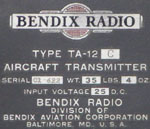
The power supply was type MP-28B which normally operated off 25 volts, but the equipment was able to operate from 20 - 28 volts, with corresponding changes in power output.
The equipment was rated for intermittent service - 5 minutes on and 5 minutes off. The set drew 16.5 amperes at 25 volts.
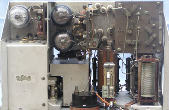
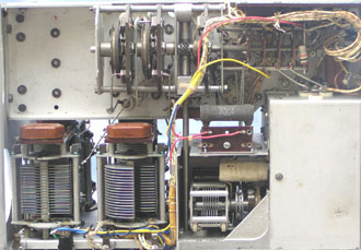
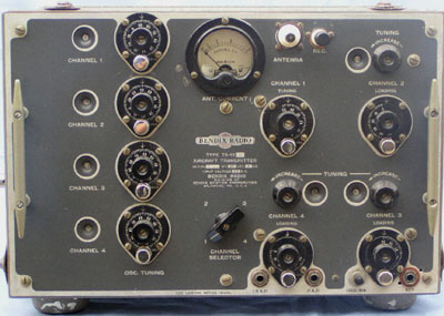
The transmitter consisted of 4 I2SK7 vfo's, one for each channel. Then followed a buffer/multiplier, consisting of a single 807. This was followed by a pair of 807 tubes in parallel.
The power supply unit also housed the modulator. This consisted of a 6N7 and 6F6 as amplifiers followed by a pair of 807's as modulators. The maximum HT voltage in the set was around 540 volts.