Click to view detailed pictures of the receiver and power supply circuits.
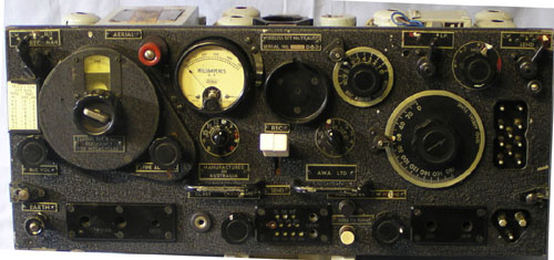
It is a combined receiver and transmitter, working over the frequency range of 4.2 - 7.5 mc/s. The circuits of the two units are so arranged that the main tuning control for the receiver is also the master oscillator for the transmitter, which makes netting easier.
The set is equipped with 9 valves, three of which are common for transmitting and receiving.
Two different H.T. power supplies are used. The Low Power unit (LP) operates the receiver and transmitter, but for additional transmitter output, the HP unit may be switched in, effectively doubling the transmitted range. The power unit outputs are 210v for the LP unit and 345v for the HP unit. Primary power for the set was 12v dc, normally provided in service life by two 6v 75Ah accumulators. On receive 2.9A of current is drawn, while on transmit 3.3A is used on LP and 6.5A on HP.
| The valve complement is: | |
| V1A 1M5G Rx RF Amp Tx Buffer | V3B 1K7G Rx Det,AVC and AF Amp. |
| V1B 1M5G Rx 1st IF Amp | V3C 1K7G Rx Output |
| V2A 1C7G Rx Freq Conv Tx Master Osc | V3D 1K7G Tx Mod and Tone Osc (MCW) |
| V2B 1C7G Tx Freq Conv and 455kc osc. | V4A 807 Tx PA |
| V3A 1K7G Rx 2nd IF Amp Tx Sidetone Detector |
The receiver IF Frequency is 455kc.
These sets were popular with hams after the war but only covered the 40 metre band. Many sets were released after the war in original packing, having never been in service as they were replaced by the No 19 set which used AC valves and included close range VHF communication and an intercom for use in armoured fighting vehicles.
The brown AWA paper condensers are a constant source of trouble and are bound to lead to set failure.
© Ian O'Toole, 2009. Page created: 25/03/07 Last updated: 11/12/2009